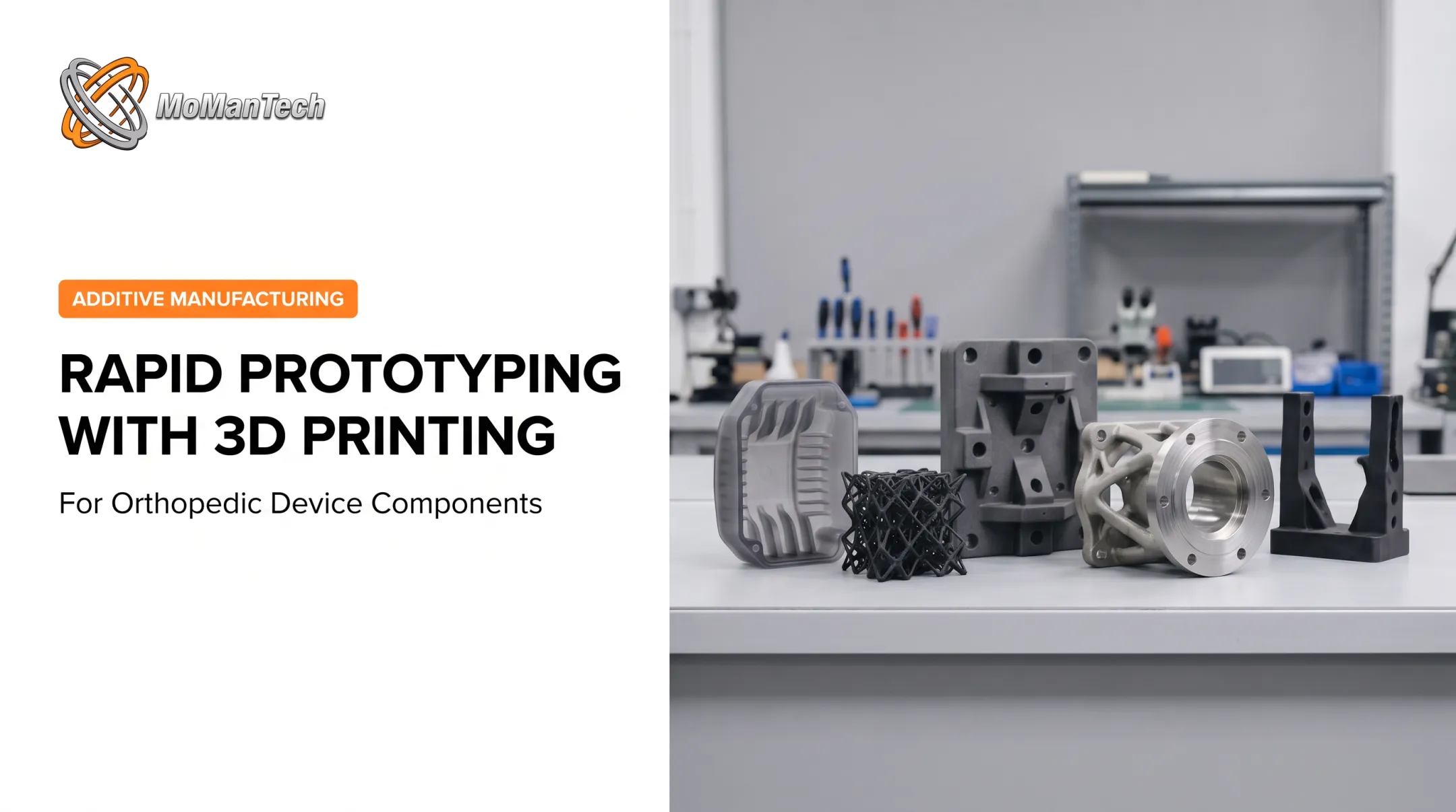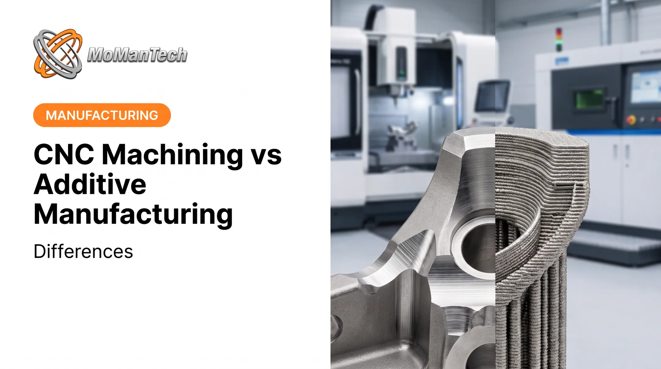

As-built surfaces carry stair-stepping, adhered powder, and support witness marks that can interfere with fit, sealing, fatigue life, or sterility. The question isn't whether to improve the surface. It's whether to engineer that improvement into the build itself or handle it with a post-treatment afterward.
Material, geometry, orientation, tolerance, and end use all drive that decision. This guide walks through how surface finish forms in AM, which post-treatments solve which problems, and how to validate the result before it reaches a customer.
Key Takeaways
- Surface finish drives fit, friction, wear, sealing, corrosion resistance, and cleanability, not just appearance
- Stair-stepping, partial fusion, spatter, and support removal each contribute differently to roughness
- Post-treatment decisions belong in the design phase, since material removal shifts tolerances and clearances
- Every finished surface needs a defined measurement method, specification, and documentation trail
What Surface Finish Means in Additive Manufacturing
Surface finish and surface roughness get used interchangeably, but they're not the whole picture. Roughness refers to the finely spaced irregularities tied to the production process itself, while waviness covers more widely spaced texture, and form error describes deviation from the part's nominal geometry.
Porosity and visible defects sit outside all three categories entirely, according to ASME's B46.1 standard.
Why Ra Doesn't Tell the Whole Story
Ra is an average absolute deviation from the mean line across an evaluation length. It's not a peak-to-valley measurement, and that distinction matters more than most drawings acknowledge. Two surfaces can share an identical Ra value while having completely different profiles: one with uniform shallow texture, another with deep isolated valleys.

That second profile might fail a fatigue test or trap bacteria in a way the first never would. Ra alone can't predict friction, sealing performance, tissue interaction, or cleanability. It's a starting point, not a complete spec.
Interpreting an Ra 6.3 Callout
A drawing note reading "Ra 6.3" tells you the parameter (Ra), the value (6.3), and usually implies micrometers. It does not tell you:
- Which drawing standard governs the callout (ASME Y14.36 vs. ISO 21920-3)
- The filter cutoff and evaluation length applied
- Whether measurement direction matters for this surface
- Whether 6.3 is a maximum, a range, or a target
Filter settings alone can shift a reported Ra value substantially for the same surface. Before accepting or rejecting a part against that number, confirm all four points with the design authority.
Where AM Roughness Comes From
Additive processes generate texture through several distinct mechanisms:
- Stair-stepping from layer-by-layer deposition on angled surfaces
- Partially fused or adhered powder clinging to the surface, especially on overhangs
- Spatter and balling from unstable melt-pool behavior
- Support interfaces leaving witness marks after removal
- Thermal distortion warping surfaces during cooling
- Internal passages that are difficult to access for cleanup
Finish also varies across a single part. Build orientation, overhang angle, feature size, position on the build plate, and powder condition all shift the result, even within one print job.
Matching Finish to Function
A bearing surface, a sealing face, and a visible exterior panel don't need the same treatment:
- Mating interfaces and threads typically need machined tolerances the as-built surface can't hold
- Sliding or bearing regions need low friction and controlled wear behavior, often via polishing or electropolishing
- Sealing surfaces need consistent roughness to maintain gasket contact
- Fluid passages need internal finish that resists turbulence and biofilm buildup
- Exterior cosmetic faces may only need blasting or tumbling
Treat each surface on its own merits rather than specifying one blanket finish for the entire part.
How Additive Manufacturing Process Choices Influence Surface Finish
Surface quality isn't an accident of the printer. It's a direct consequence of decisions made before the build even starts.
Orientation and Layer Thickness
Overhangs come out rougher than vertical walls because powder supports a molten pool far less effectively than solid material underneath it. NIST-authored research on laser powder bed fusion of Inconel 718 and AlSi10Mg identifies surface angle as one of the strongest predictors of roughness across platforms.
Layer thickness compounds the effect. Thicker layers create more pronounced stair-stepping on angled features, while file pixelation can turn surfaces meant to be smooth into unintentionally stepped ones.
Where tolerance allows, orient critical surfaces vertically or near-vertically, and flag the ones that can't be reoriented for post-processing.
Energy Settings, Scan Strategy, and Powder
Laser power, scan speed, hatch spacing, and powder particle distribution all interact in ways that resist simple rules. Research findings make that clear:
- Volumetric energy density and contour offset interact on 316L PBF; higher energy and wider offsets can promote dross and raise Sa
- Smallest particle fraction in Inconel 718 powder correlates with roughness; particles above the median size do not
Don't assume a published "optimal" parameter set transfers across machines, alloys, or geometries. Ask your manufacturing partner for process-specific validation data.
Powder Bed Fusion vs. Directed Energy Deposition
Both families produce rougher surfaces on overhangs and near supports, but the mechanisms and typical values differ:
| Process | Typical as-built roughness context |
|---|---|
| PBF (laser-based, Ti-6Al-4V) | Ra 9–12 µm as-built; manufacturer datasheet condition |
| DED (powder-fed, 316L/IN718 single tracks) | Roughness ranging roughly 3–43 µm depending on energy input |

These figures come from different test setups and aren't directly comparable as a head-to-head benchmark. In practice, DED tends to deposit more material per pass with coarser texture, while PBF offers finer control at the cost of build speed. Choose based on the part's geometry and finishing plan, not a single roughness number.
Support Removal and Pre-Finishing Steps
Before any finishing operation begins, the part goes through support removal, stress relief, heat treatment, and depowdering. Each of these can shift distortion, introduce new witness marks, or leave residual material in internal passages. Build this sequence into your process plan rather than treating it as an afterthought squeezed in before shipping.
On the drawing, separate the as-built specification from the final post-processed specification. Call out which surfaces stay as-built and which require treatment so inspection has no ambiguity.
Common Post-Treatments for Additively Manufactured Parts
No single treatment fits every AM surface. Here's how the main options compare.
Mechanical and Abrasive Methods
CNC machining, turning, milling, and grinding remain the go-to choice for accessible surfaces needing controlled geometry. Turning operations on AM titanium have achieved finish-cut results around Ra 1 µm or below, but these methods struggle with thin walls, lattice structures, and features buried deep inside a part.
Deburring and edge conditioning are separate operations from general finishing. They remove sharp edges, support remnants, and loose material, but must be controlled carefully to avoid rounding critical dimensions unintentionally.
For internal geometries machining can't reach, abrasive flow machining (AFM) pushes abrasive media through channels and cavities.
According to research from UT Austin, AFM on laser powder bed fusion Ti-6Al-4V channels improved roughness by roughly 40% in larger channels without significant diameter change. Smaller channels and bends saw similar roughness gains but a 6% diameter increase, a trade-off worth planning for during design.
Chemical and Electrochemical Methods
Chemical polishing, electropolishing, and electrochemical machining can treat complex or internal surfaces mechanical tools can't access.
One study on electron beam melted Ti-6Al-4V showed average roughness dropping from 24.1 µm to 4.5 µm under a tested electropolishing condition, with improved corrosion resistance as a side benefit. Over-treatment, however, can introduce nanopitting and actually degrade corrosion performance.

Before specifying these methods, confirm alloy compatibility, dimensional control limits, chemistry management, and waste handling requirements with your provider.
Thermal and Coating-Based Methods
- Heat treatment and stress relief primarily address microstructure and residual stress, not surface texture
- Laser polishing and remelting flow peak material into valleys; studies report Sa 0.8 µm on cobalt-chrome from Sa 18 µm, with cracking risk on titanium under continuous-wave polishing
- Shot peening improves fatigue resistance and introduces compressive residual stress, with surface roughness as a secondary effect
- Coatings and passivation can add thickness or alter biocompatibility, so account for their dimensional contribution during design
Blasting, tumbling, and hybrid additive-subtractive workflows round out the toolkit. All of them can obscure underlying defects if used as a shortcut rather than a validated step, so pair any cosmetic treatment with inspection underneath.
MoManTech's finishing line reflects this range of needs: a VibraHone mass tumbler, rotary and manual blast cabinets, and buffing and sanding equipment handle mechanical finishing, while an ESMA ultrasonic cleaning and citric passivation line addresses cleaning and corrosion-resistance requirements for orthopedic components.
How to Select and Validate a Post-Treatment
Choosing a treatment starts with five questions, not a catalog of options:
- What function does the surface perform? Bearing, sealing, cosmetic, and tissue-contact surfaces all demand different outcomes.
- What finish and dimensional tolerances are required? Confirm both before picking a method.
- Is the surface accessible? Internal channels rule out line-of-sight tools like CNC polishing.
- What material and AM process were used? Alloy and build method both limit which treatments apply.
- What evidence and documentation are required? Medical and aerospace applications need more than a visual check.
Every treatment trades something for roughness reduction. Chemical and abrasive methods remove material, which can round edges, shift clearances, or distort thin features. Peening and blasting can leave trapped media behind.
Build these trade-offs into your tolerance stack-up before production, not after a batch fails inspection.
Specify critical and noncritical surfaces separately on drawings, and define:
- Datum features and masking requirements
- Machining allowances and allowable dimensional change
- Inspection locations tied to each critical surface
A sound validation sequence runs from test coupon through first article:
- Confirm treatment parameters on the coupon
- Measure the surface finish against the specified target
- Check dimensions for allowable change
- Verify cleanliness before release
- Monitor production lots against that baseline

Reference the applicable surface-texture and AM standards (ASME Y14.36 for drawing symbols, ASTM F3624 for powder bed fusion surface characterization) rather than inventing a one-size-fits-all threshold.
Your quality record should document:
- Material and build details
- Treatment parameters and equipment used
- Measurement method and calibration status
- Inspection results and lot traceability
MoManTech's OGP Flash 302 vision system, which combines CMM and laser measurement, supports this kind of dimensional and surface verification across prototype and production lots.
Designing for Surface Finish and Post-Processing
Finishing decisions made after the build is printed cost more than those locked in during design review. Orientation, support strategy, machining access, fixturing, and inspection access all belong in the CAD stage.
Identify finishing needs early by flagging which surfaces need machining or treatment stock. Add allowances without compromising thin walls, lattice structures, small holes, or threads. Removing even a fraction of a millimeter can shift a delicate feature out of tolerance.
Internal channels, blind cavities, and intersecting passages present the hardest cases. Conventional tools simply can't reach them. Two paths solve this:
- Redesign the geometry to open access, such as adding a secondary port for abrasive flow
- Select a treatment capable of reaching enclosed features, such as chemical or electrochemical methods
MoManTech's additive prototyping service includes custom fixturing designed specifically for these internal operations, keeping parts stable during secondary finishing without distorting critical features.
Drawing and Communication Checklist
Before a part goes to production, confirm the drawing specifies:
- Finish symbol and Ra (or other) parameter
- Measurement direction and sampling method
- Which areas are treated vs. as-built
- Edge condition and datum scheme
- Dimensional tolerance after treatment
- Cleanliness requirement and documentation expectations
Special Considerations for Medical-Device Parts
Orthopedic components don't have one finish priority. A surface that contacts tissue needs different treatment than one that mates with another component, guides an instrument, or supports fixation.
Risk assessment for these parts needs to evaluate more than roughness:
- Residual powder trapped in geometry
- Burrs and support witness marks
- Chemical residues from etching or electropolishing
- Corrosion behavior under physiological conditions
- Compatibility with planned coatings or passivation
The FDA's guidance on additively manufactured devices recommends building worst-case complex geometry into cleaning validation. That validation should rest on the final finished device after all other processing steps, according to FDA's AM guidance.

Engineering suitability and regulatory acceptance are separate questions. Device classification, biological evaluation, and sterilization validation requirements vary by product and need their own dedicated review.
Surface finish decisions on orthopedic components sit at the intersection of engineering, biology, and regulation. None of the three can be addressed in isolation.
A manufacturing partner's quality infrastructure matters as much as its equipment list. MoManTech is ISO 13485:2016-certified and works exclusively with orthopedic surgical device OEMs across spine, trauma, large joint, and foot and ankle components.
When an OEM's additive design needs hybrid machining, finishing, or inspection to meet a drawing's final specification, MoManTech supports that move from prototype to production with design-for-manufacturability review, machined interfaces, and documented production planning.
Frequently Asked Questions
What does a Ra 6.3 surface finish mean?
It specifies an average roughness value of 6.3, typically in micrometers, but the governing drawing standard, measurement direction, and acceptance convention must be confirmed before interpreting or accepting the part.
What is the difference between as-built and post-processed surface finish?
As-built finish is whatever the additive process produces directly off the machine. Post-processed finish results from subsequent machining, polishing, chemical, abrasive, or thermal treatment applied afterward.
Which post-treatment is best for additive manufacturing parts?
There's no universal best option. The right choice depends on alloy, geometry, surface accessibility, required finish and tolerance, production volume, and validation requirements specific to the part.
Can post-processing change the dimensions of an AM part?
Yes. Machining, polishing, chemical removal, and blasting can all alter dimensions, round edges, shift clearances, and change the surface layer, so allowances need to be planned during design.
How is surface roughness measured on an additive manufactured part?
Both contact (stylus) and noncontact (optical) methods apply, depending on surface accessibility and geometry. Measurement direction, instrument calibration, and inspection of representative critical surfaces all affect the result.
Do medical-device AM parts always need a smooth surface finish?
No. Requirements vary by function and surface location. Final finish requirements come from engineering, quality, materials, cleaning, and applicable regulatory review, not a single blanket rule.