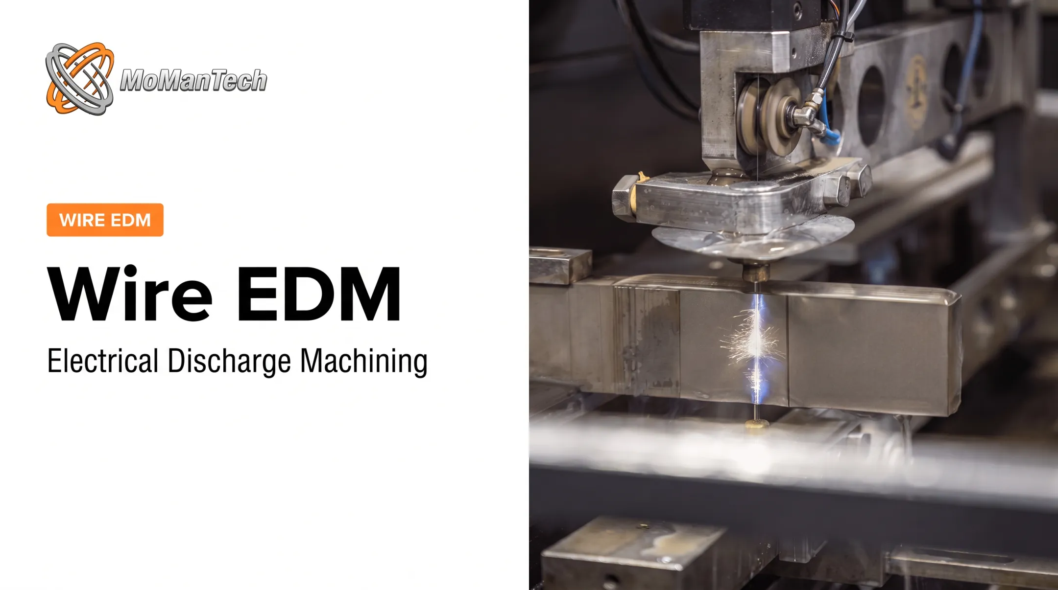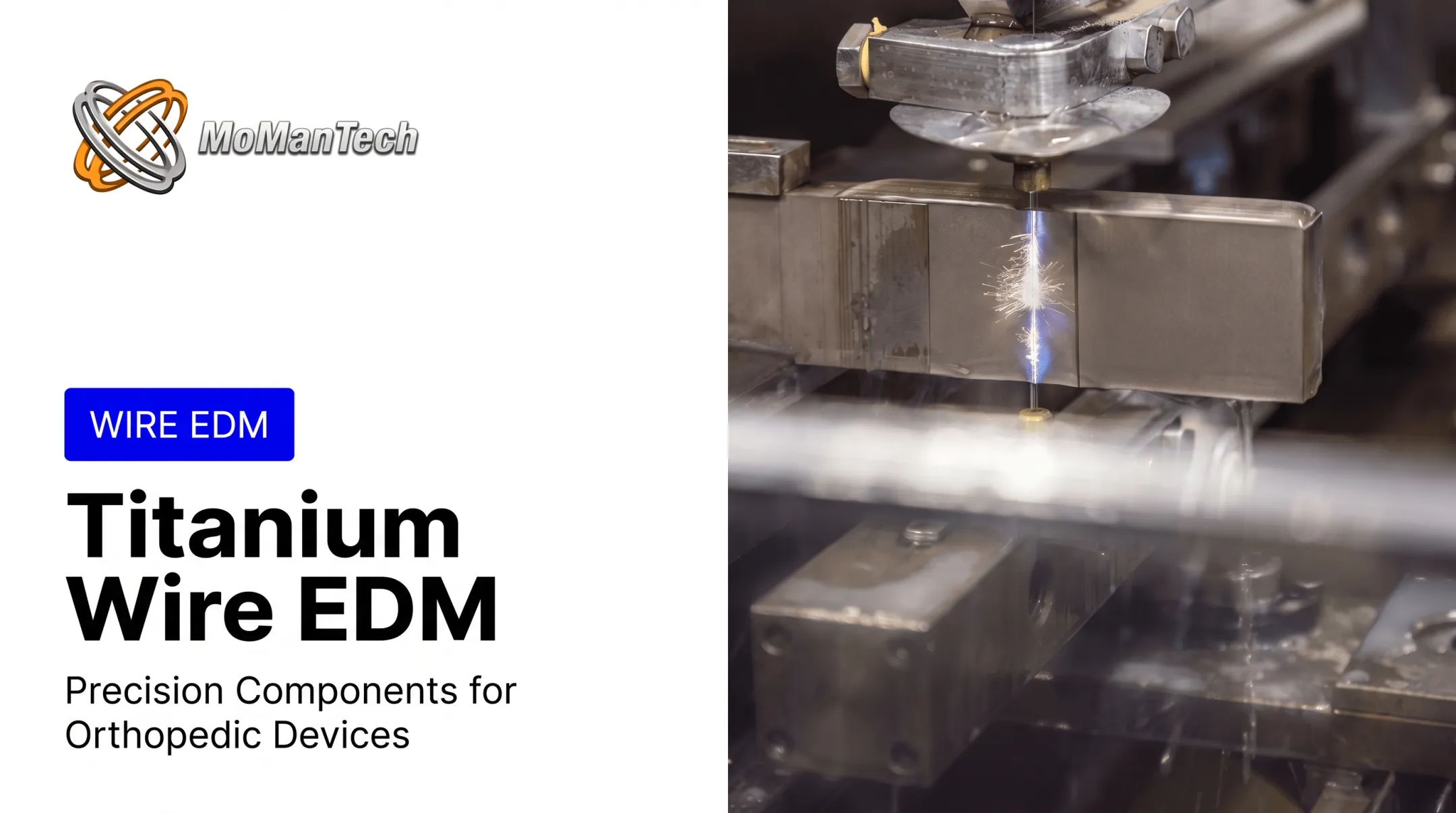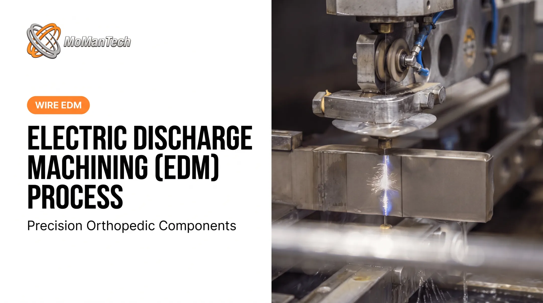

Electrical discharge machining, specifically wire erosion, uses a continuously moving wire electrode and controlled electrical sparks to erode conductive metal along a programmed path. There's no cutting force, no tool deflection, and no practical limit on how hard the material is.
This matters more than it used to. Makino's 2022 announcement of its U6 H.E.A.T. Extreme wire EDM reported roughing-rate increases of up to 300% over standard 0.010-inch brass wire, a sign of how fast this corner of precision manufacturing is moving. That kind of gain shows up directly in mold and die shops, aerospace suppliers, electronics manufacturers, and medical-device machinists who all depend on wire EDM for parts that simply can't be made any other way.
If you've seen the terms wire EDM, wire erosion, wire cutting, and spark erosion used interchangeably and wondered whether they're the same thing, you're not alone. This guide breaks down what the process actually does, how it runs stage by stage, which materials and jobs suit it, and where its limits are.
Key Takeaways
- Wire EDM is a CNC-controlled, non-contact process that erodes conductive metal using sparks from a continuously fed wire
- Deionized water manages the spark gap, cools the cut, and flushes away eroded debris
- A typical job moves through setup, wire threading, rough cutting, skim passes, and final inspection
- The process suits hardened, intricate, delicate, or tight-tolerance conductive parts, not nonconductive materials or every high-volume job
What Is EDM Wire Erosion?
Wire EDM, also called wire-cut EDM, wire cutting, or spark erosion, is a thermal material-removal process. A thin metal wire, charged with electrical pulses, erodes a conductive workpiece as it travels a programmed path. The material doesn't get cut in the traditional sense; it gets vaporized, a microscopic spark at a time.
That distinction matters for a simple reason: there's no mechanical force involved. Shops turn to wire EDM when a part needs:
- Intricate profiles or narrow slots that a milling tool can't reach
- Sharp internal corners without added radius
- Machining on hardened material that would wreck conventional cutters
What Wire EDM Is Not
It's easy to lump wire EDM in with other "non-traditional" cutting methods, but the mechanics differ sharply.
- Milling and laser cutting rely on mechanical or thermal contact with broader tool paths; wire EDM erodes material with zero mechanical contact
- Waterjet cutting uses abrasive particles and pressure, not electrical discharge
- Sinker EDM uses a shaped electrode to plunge into material and form a cavity; wire EDM uses a moving wire and typically produces through-cuts, not blind pockets
- Small-hole EDM drills a starting hole, sometimes as a preparatory step before wire EDM begins
The Core Components
Every wire EDM setup relies on five elements working together:
- Wire electrode
- Workpiece
- CNC motion system
- Pulsed power supply
- Dielectric fluid (almost always deionized water)
Change any one of those, and the cut changes with it.
Machine configurations vary by job. Some run submerged in a dielectric tank; others use nozzle-flushed cutting for taller or more complex parts. Technical comparisons from builders such as Sodick often weigh flushing consistency against setup flexibility when choosing between the two.
Standard wire EDM handles general profile work, while micro-wire EDM uses finer wire for tiny features. Straight-wall cutting is the default, but U-V axis control lets the machine taper or vary the profile through the thickness of the part.

How Does EDM Wire Erosion Work?
Wire EDM runs as a controlled sequence: the machine positions and feeds the wire, fires repeated sparks, manages the gap between wire and workpiece, clears debris, and refines the cut before anything gets inspected.
Initiation
Before a single spark fires, the workpiece has to be set up correctly. That means establishing a datum, clamping the part securely, and checking alignment, flatness, and perpendicularity.
For enclosed profiles, like an internal slot that doesn't connect to an outer edge, a starting hole usually has to be drilled first (sometimes using small-hole EDM). Jobs with accessible edges can skip that step entirely.
Once the part is positioned:
- The wire threads through upper and lower guides
- Tension gets set to the correct specification
- The wire passes through the starting hole or edge access point
- The program gets verified against the part geometry
Automatic wire threading has become standard on newer machines specifically to cut downtime after a wire break. Workholding, wire condition, and guide alignment all have to check out before the actual cutting starts; skip any of them and the cut drifts.
Core Operation
Here's the mechanism in plain terms: a voltage difference builds between the wire and the conductive workpiece until it jumps the gap as a spark. That spark melts or vaporizes a microscopic amount of material. Repeat that thousands of times a second, and material erodes steadily along the programmed path.
The CNC system drives the wire through the X-Y path and, on machines with U-V axis control, tilts the wire to produce tapers or changing cross-sections. No part of the wire ever touches the workpiece.
Several variables shape the outcome:
- Wire diameter and resulting kerf width
- Spark-gap compensation settings
- Material conductivity and workpiece thickness
- Pulse settings and programmed feed rate
The wire itself gets continuously fed and consumed, so the active cutting section stays fresh rather than degrading mid-cut. A first rough pass removes the bulk of the material quickly; it's followed by one or more skim passes that trim size, improve straightness, and refine surface quality. (Wire diameters and specific operating ranges vary by machine model, so check manufacturer specifications rather than assuming a universal figure applies.)

Regulation and Control
Behind the scenes, servo controls constantly monitor discharge behavior and adjust wire position and spark-gap conditions in real time. This is what keeps the wire from ever actually contacting the part.
Deionized water does three jobs at once: it insulates the gap until the voltage is right for controlled breakdown, cools the cutting zone, and flushes eroded particles out of the kerf. According to SME's study guide, wire EDM relies on a series of DC discharges, with EDM power supplies usually described as pulsed direct current rather than simple continuous household AC or DC. That pulsing is what allows controlled, repeatable erosion instead of a sustained arc.
Several conditions affect how stable that process stays:
- Flushing pressure and water resistivity
- Filtration quality and fluid temperature
- Debris buildup in the cutting gap
- Wire tension consistency
When sparks become unstable, debris accumulates, or tension runs too high, machines respond automatically by adjusting feed rate or pausing to clear the gap. Left unchecked, these disruptions lead to wire breakage and inconsistent recast formation on the cut surface.
Output and Result
What comes off the machine is a precisely cut profile, straight-walled, tapered, or containing narrow slots and complex internal features, depending on the wire path and axes used.
Rough cuts prioritize speed over finish. Skim passes run at lower energy specifically to improve dimensional accuracy and surface quality, since each lower-energy pass removes less material and leaves less thermal disturbance behind. Sodick's published specifications list accuracy down to +/-3 micrometers and surface finish as fine as 0.36 micrometer Ra, figures tied to that specific machine platform rather than a guaranteed outcome across every wire EDM setup.
One detail worth flagging: wire EDM can leave a microscopic recast layer or heat-affected zone on the cut surface. A 2021 Ti-6Al-4V study published in the Journal of Materials Engineering and Performance identified distinct flaky, recast, and heat-affected layers forming during the cut, each from a different thermal mechanism. For fatigue-sensitive, implantable, or coated components, that surface condition matters as much as the dimensional tolerance.
After cutting, the part typically goes through:
- Slug removal and cleaning
- Deburring verification and visual examination
- Dimensional inspection and surface-finish measurement
- Documentation tied to the job traveler
At MoManTech, that inspection step runs on an OGP Flash 302 vision system with CMM and laser measurement, paired with a 14-inch Mitutoyo height gauge, so dimensional data gets captured before a part ever leaves the ISO 13485:2016-controlled process. For orthopedic components, that documentation isn't optional. It's part of what makes the part traceable and acceptable downstream.
Where EDM Wire Erosion Is Used
Wire EDM typically runs late in the manufacturing sequence, after material prep and programming, during final profile cutting or toolmaking, followed by cleaning, inspection, and assembly.
Conditions That Favor Wire EDM
It's the right call when a part has:
- Electrically conductive material, including hardened or difficult-to-machine alloys
- Intricate two-dimensional or tapered profiles
- Thin or delicate sections that mechanical force would distort
- Sharp internal corners that cutting tools can't replicate
Common Applications
| Sector | Typical use |
|---|---|
| Mold and die tooling | Fine detail in pre-hardened stamping and blanking dies |
| Aerospace | Cutting Inconel and other heat-resistant alloys |
| Electronics | High-precision tooling for connectors and micro components |
| Medical devices | Sophisticated geometries for surgical and implant-adjacent parts |
Orthopedic components carry extra weight here. Geometry, surface condition, inspection records, and traceability all need tight control, since these parts eventually interface with the human body. That's the exact space MoManTech works in, machining spinal, trauma, large joint, and foot/ankle components on Chmer GX360L and Fanuc OA wire EDM equipment, with every part passing through a documented inspection process before it ships.

Where It Falls Short
Wire EDM isn't the answer for every job. Nonconductive materials can't be processed directly. Enclosed profiles need through-cut access or a pre-drilled starting hole. Very high-volume simple shapes often make more economic sense on a different process entirely, and unusually thick or complex workpieces may need a feasibility review before committing to a program.
If you're evaluating a manufacturing partner for wire EDM work, ask about:
- Design-for-manufacturability support during early planning
- Inspection equipment and documented quality processes
- Prototype and production capacity, from 1-10 units to 100+
- Lead-time control and relevant certifications like ISO 13485:2016
Conclusion
Wire EDM removes conductive material through repeated, controlled electrical discharges rather than mechanical contact. CNC motion, dielectric management, and spark-gap regulation determine exactly what that cut looks like when it's done.
Before committing to the process, confirm:
- Conductivity and material thickness
- Geometry and starting-hole access
- Tolerance and finish requirements
- Inspection needs and production volume
Those factors, more than any single spec sheet, decide whether wire EDM is the right fit.
Orthopedic OEMs planning intricate implants or instruments can talk through manufacturability, quality documentation, and production requirements with MoManTech. That conversation helps identify the most appropriate precision-machining approach for the component.
Frequently Asked Questions
What is the process of wire EDM?
The workpiece is clamped and aligned, then the wire threads through a starting hole or edge. CNC-guided spark erosion cuts in deionized water, with a rough pass, skim passes, and final inspection.
Is EDM AC or DC?
EDM uses controlled pulsed direct current between the wire and workpiece. That differs from the continuous alternating current in standard household circuits.
What materials can be cut with EDM wire erosion?
The workpiece has to be electrically conductive. Common examples include tool steel, stainless steel, titanium, carbide, and copper alloys. Plastics and most ceramics can't be cut directly since they lack the conductivity the process requires.
Is wire erosion the same as wire EDM?
Yes. Wire erosion, wire EDM, wire-cut EDM, and wire cutting all describe the same general process. "Spark erosion" is sometimes used more broadly to cover other EDM methods beyond wire cutting alone.
What is the difference between wire EDM and sinker EDM?
Wire EDM uses a continuously fed wire to create through-cut profiles and contours. Sinker EDM uses a shaped electrode that plunges into the material to form cavities or three-dimensional impressions instead.
How precise is EDM wire erosion?
Precision depends on machine capability, wire diameter, material, thickness, flushing, and finish passes. Sodick's published specs cite accuracy down to +/-3 micrometers on qualifying setups; real results vary by job and equipment.