
Many device OEMs discover this the hard way: a design that passed review looks nothing like the part that comes off the machine. Features that worked fine at a larger scale suddenly become difficult to cut, measure, and repeat consistently from lot to lot.
Precision medical micromachining addresses this gap. It's the controlled production of miniature components and fine features for regulated medical devices — and it demands far more than a small end mill and a capable CNC machine. This article covers what the discipline actually involves, where it applies, and how to choose a partner who can deliver it reliably.
Key Takeaways
- Micromachining success depends on process control, material expertise, and inspection, not only small tooling
- Thin walls, small bores, and fine threads raise burr, deflection, and dimensional-drift risk
- Material choice (titanium, stainless, cobalt-chrome, PEEK) drives machinability and finish
- ISO 13485:2016 is a baseline, not proof a given part will meet spec
- A complete RFQ with CAD, tolerances, and inspection needs shortens the path to production
What Is Precision Medical Micromachining?
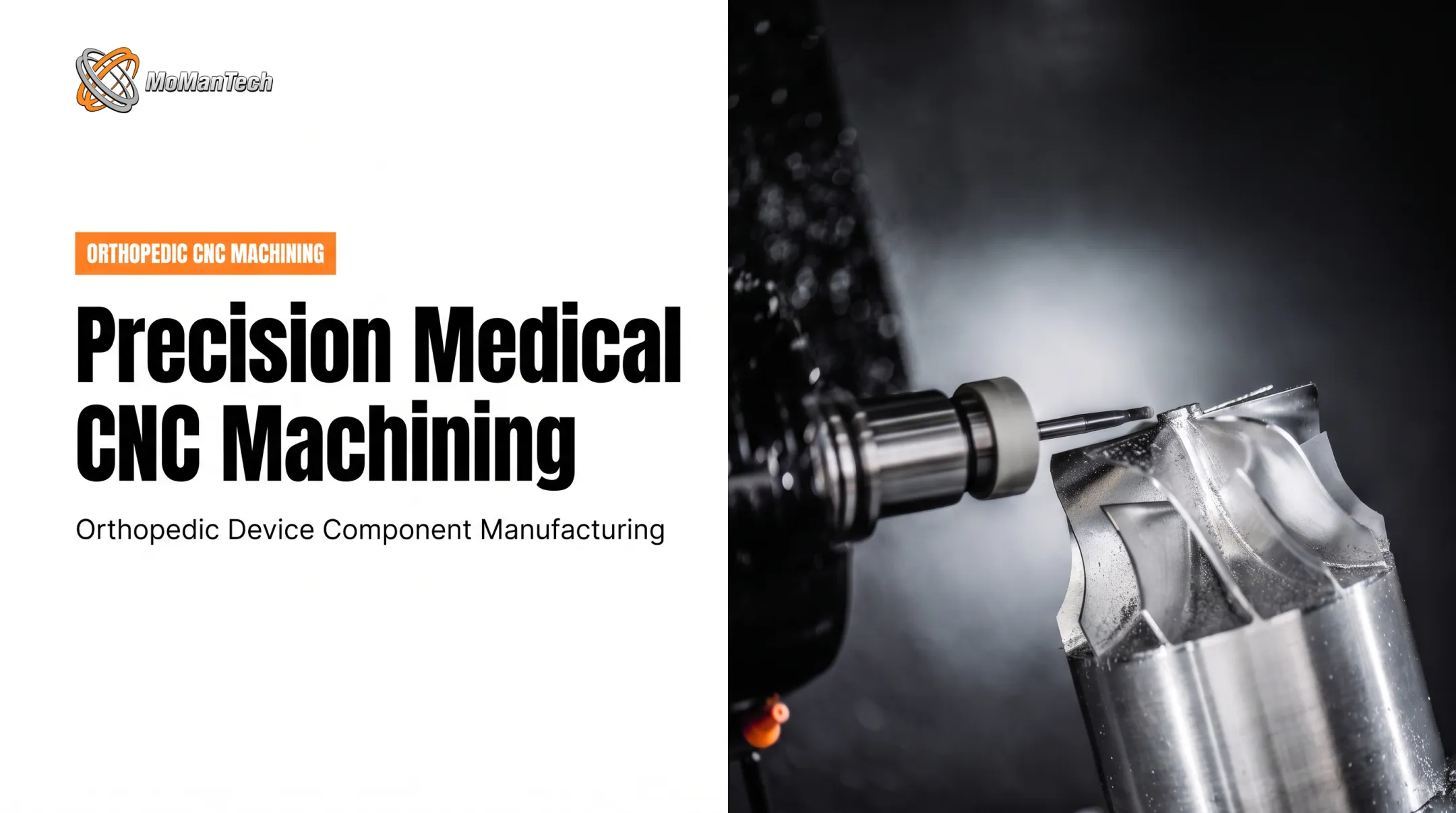
Conventional CNC machining and micromachining aren't separated by a single tolerance number. A 2021 technical review defines micro-milling by cutting-tool diameters roughly 1 to 1,000 microns, a scale where tool stiffness, cutting-edge radius, and burr formation behave differently than they do at conventional sizes. That's a description of the tool, not a promise that every feature on a part must fall under a millimeter.
In practice, a part doesn't need to be tiny overall to require micro-scale process planning. A slender projection, a narrow slot, or a thin wall on an otherwise standard-sized implant component can introduce the same risks: deflection, chatter, and burrs that ordinary tolerance callouts don't address.
Precision Means More Than One Number
Quoting a single tolerance tells you almost nothing about whether a component will actually work. Real precision gets evaluated across several dimensions:
- Accuracy: does the part match the drawing, feature by feature?
- Repeatability: does the 50th part match the 1st?
- Surface integrity: are edges clean, free of tears or recast layers?
- Burr control: are critical passages and mating surfaces free of debris risk?
- Process stability: does the setup hold up across a full production run?
Medical applications raise the stakes on all five. A missed radius on a spinal component can affect implant fit. A burr inside a cannulated feature can compromise cleanability or sterilization. Fatigue performance on a trauma plate depends on surface condition as much as geometry—and none of that shows up on a single-dimension inspection report.
Why Medical OEMs Use Micromachining
Those risks are exactly why medical OEMs reach for micromachining when geometry is still in flux. Direct-from-CAD machining lets them build prototypes, first articles, and design iterations without committing to dedicated molding or stamping tools first. That matters most for:
- Patient-specific or anatomy-driven geometries
- Low-to-medium production volumes
- Designs still moving through iteration before a final release
Early collaboration with the machinist changes outcomes here. A shop that reviews the model before it's frozen can flag tool-access problems, suggest a radius change that avoids a secondary operation, or catch a feature that's technically machinable but expensive to inspect.
MoManTech builds this kind of design-for-manufacturability review into its planning-stage work with OEMs, smoothing the handoff from prototype quantities of 1–10 units into repeat production runs of 100 or more.
Applications of Precision Medical Micromachining
Miniature features show up across the orthopedic device landscape, each with a different functional job to do.
Spinal, trauma, and large-joint components. Fixation hardware, trauma plates, and joint components rely on precisely machined threads, mating interfaces, and contoured surfaces. A thread that's slightly out of spec can affect how a construct seats; a contoured surface with the wrong finish can affect how it interfaces with surrounding tissue or another component.
Surgical instruments. Small jaws, cutting features, locking interfaces, and shafts on minimally invasive tools all depend on tight clearances that allow reliable movement while staying cleanable between uses. Surface finish here isn't cosmetic. It directly affects function and reprocessing.
Delivery systems and instrument mechanisms. Orthopedic instrument mechanisms and related miniature assemblies often include parts suited to machining, though not every geometry belongs on a lathe or mill. Some features fit molding, laser processing, or additive methods better—and sorting that out is part of a sound DFM review.
Low-volume and customized products. Fixed tooling rarely makes sense for prototypes, first articles, or anatomy-driven designs produced in small batches. Machining fills that gap without forcing a tooling investment before volumes materialize.
A Published Example of DFM in Action
A 2026 case reported by BONEZONE describes an OEM team working through design-for-manufacturability review on a milled spinal spacer. Changing the radii on the part allowed the shop to use standard tooling instead of complex 3D contouring, reportedly saving nearly 15 minutes of machining time per part.

A related knee-component review in the same account consolidated several tight-tolerance features into one datum-driven feature, cutting setups and inspection steps.
Neither case names the OEM or claims a universal cycle-time benchmark. Both still illustrate a pattern worth asking your machining partner about: what changes when the drawing gets reviewed before it's finalized, not after?
MoManTech supports this kind of iteration directly, offering prototype quantities as low as 1–10 units alongside 3D-printed prototyping in stainless and titanium, so design changes can be tested physically before committing to a full production run.
Key Technologies and Materials
Process selection depends on part geometry first, machine capability second.
| Process | Best suited for | Watch for |
|---|---|---|
| Swiss-type turning | Slender, bar-fed features close to the guide bushing | Bar-stock fit; complex surfaces may need another process |
| Precision milling | Accessible pockets, radii, non-axisymmetric features | Cutter deflection, burr formation on small features |
| Multi-axis machining | Surfaces needing multiple tool orientations in one setup | Confirm it actually reduces setups for this part |
| Wire EDM | Intricate profiles in conductive material | Requires conductive stock and wire-accessible geometry |
A 2023 Production Machining account describes a shop moving a small, complex meniscus-surgery component from Swiss turning to five-axis machining when the original process couldn't meet the required surface finish. Process selection should be justified by the specific feature, not by what machine happens to be available.
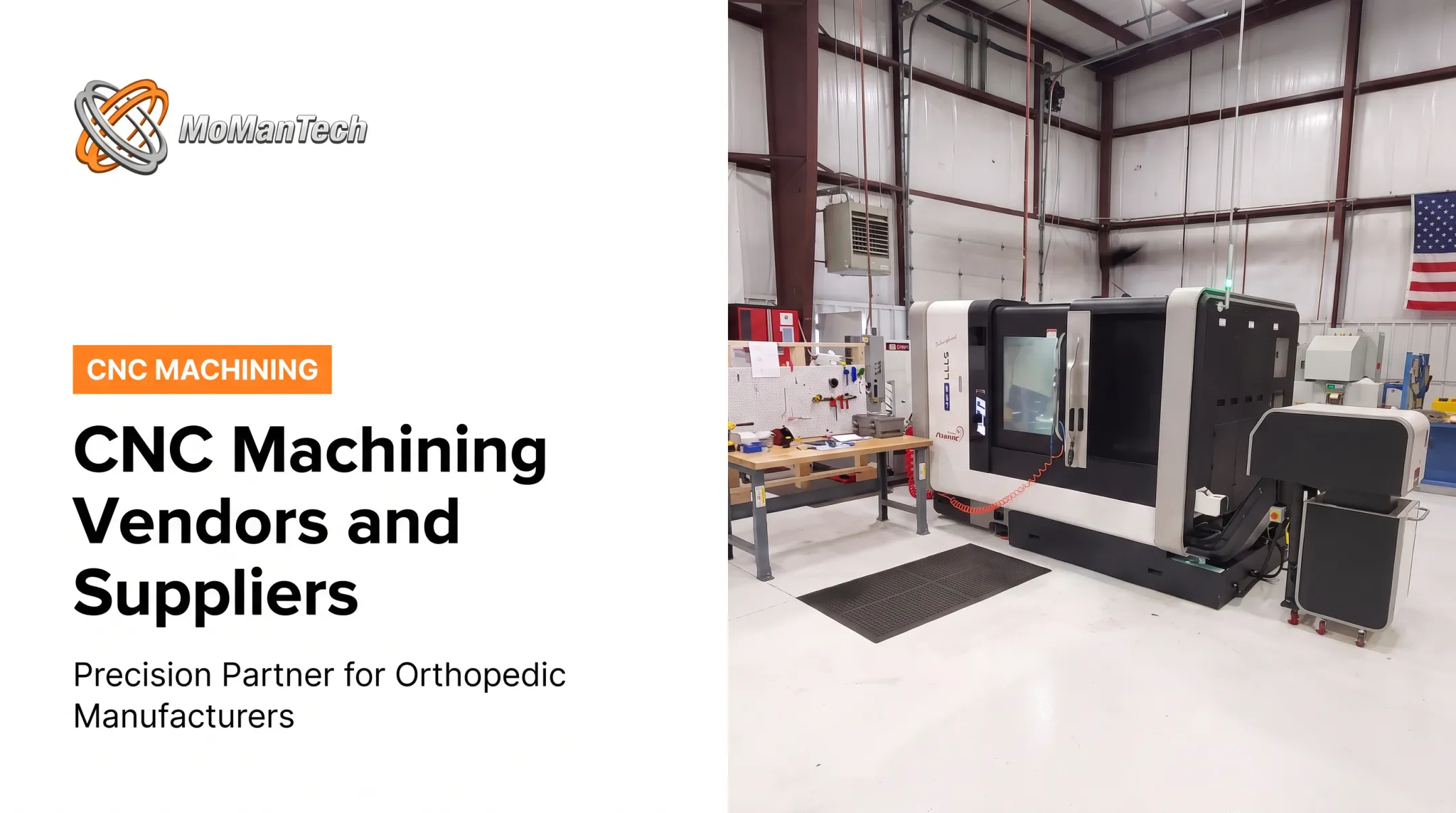
MoManTech runs this kind of mixed capability set: 6-axis Mazak Integrex machines, a 9-axis Swiss platform, dedicated Swiss lathes, and wire EDM, so the process route gets chosen based on the part rather than forced to fit a single machine.
Material Trade-Offs
Common orthopedic materials behave very differently under the cutter:
- Titanium alloys generate heat that doesn't dissipate easily, which can accelerate tool wear if speeds and feeds aren't matched to the alloy.
- Stainless steels can work-harden quickly; feeding too lightly risks cutting through an already-hardened zone instead of fresh material.
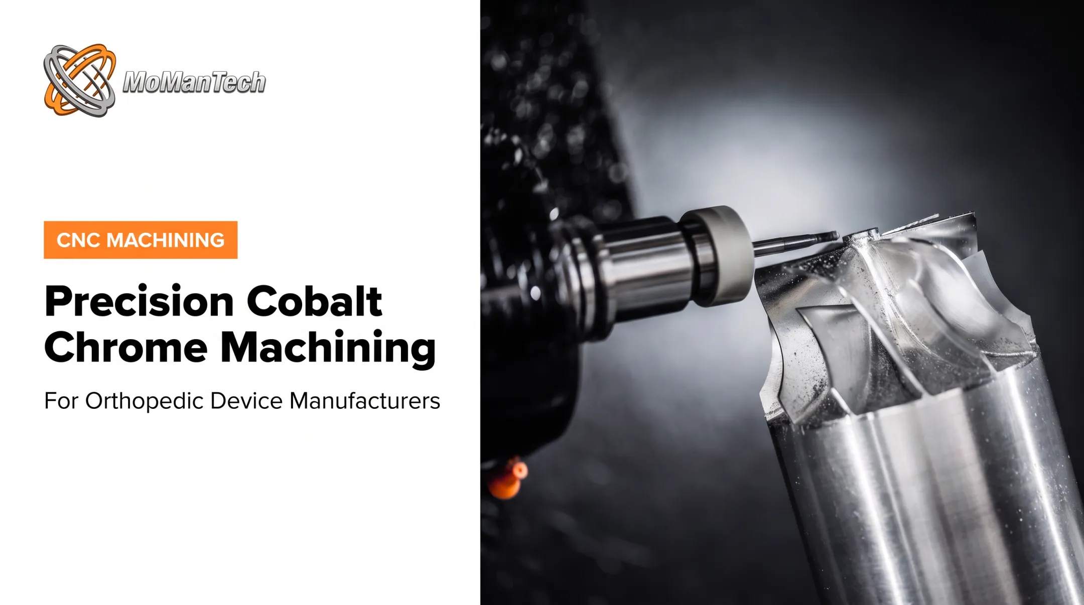
- Cobalt-chrome alloys are abrasive and prone to vibration issues, demanding rigid setups and careful tool selection.
- PEEK and medical-grade polymers deform and deflect under cutting pressure in ways metals don't, requiring different clamping and feed strategies.

Material standards matter as much as the alloy name. ASTM F136 covers wrought Ti-6Al-4V ELI for implant use; F899 covers stainless steel for surgical instruments — not implant stock. Confirming the exact alloy, product form, and standard on the material certificate avoids a mismatch that a visual inspection won't catch.
Design and Process Challenges
Small scale amplifies failure modes that are easy to ignore on larger parts. Micro-milling research links low feed-to-edge-radius ratios to increased burr formation, and identifies cutter deflection as a direct cause of form-accuracy loss. Heat, vibration, and tool wear all compound faster when the cutting tool itself is only a few hundred microns in diameter.
Design Choices That Affect Manufacturability
A handful of design decisions drive most of the downstream cost and risk:
- Internal corner radii: tighter radii demand smaller tools, which deflect more and wear faster
- Tool access: deep, narrow features may exceed what a standard reach can achieve cleanly
- Thin walls: flex or warp under cutting force and throw off final dimensions
- Small holes and high-aspect-ratio features: drift off-axis easily and are harder to inspect
- Workholding: delicate geometries need fixturing that does not distort the part
Material condition matters just as much as geometry. Grain structure, residual stress, and heat treatment all influence dimensional drift after machining. A part can measure correctly off the machine and still shift afterward if internal stresses were not accounted for.
A Practical Process-Control Sequence
A disciplined sequence catches problems before they become scrap:
- Review the drawing and flag critical features with engineering
- Verify material against the certificate and governing standard
- Match CAM and tooling strategy to the specific geometry
- Machine under controlled conditions with in-process monitoring
- Deburr, finish, or passivate as the material and spec require
- Check critical features dimensionally during the run
- Complete final inspection and release documentation

MoManTech's quality process follows this sequence closely. The shop pairs an OGP Flash 302 vision system and CMM/laser measurement with ultrasonic cleaning and citric passivation lines, so inspection happens at multiple points rather than only at the end.
That multi-point discipline also shows up in cost and schedule. Complex geometry, low quantities, and tight tolerances all add engineering and inspection time a simple part would not need. Prototype pricing and production pricing reflect different economics: tool life and setup amortization change sharply once volumes move from 1–10 units to 100 or more.
Quality, Compliance, and Choosing a Supplier
ISO 13485:2016 establishes a quality-management framework for organizations involved in medical device design, production, and servicing. It's a reasonable baseline to expect from any contract machining partner. Certification alone doesn't prove a specific part will meet its drawing requirements. That proof comes from documented evidence tied to the actual component.
What to Look For in a Supplier
A useful evaluation checklist covers:
- Orthopedic-specific experience, not general machining background
- Prototype and first-article support at low quantities
- Active DFM communication before the design is frozen
- Inspection capability matched to the smallest critical feature
- Documented material traceability and lot control
- Scalability from prototype to production without a second qualification cycle
- Automation or capacity that supports realistic lead times
MoManTech fits this profile as an ISO 13485:2016-certified contract manufacturer working exclusively in orthopedic components for spine, trauma, large joint, and foot/ankle applications. The shop supports prototype quantities of 1–10 units through production runs of 100-plus, backed by design-for-manufacturability consultation and comprehensive inspection on every part that leaves the facility.
Automated loading and unloading on select machines also supports longer unattended runs, which helps with lead-time responsiveness as volumes grow.
Once suppliers clear this bar, RFQ quality drives how fast and accurate their quotes will be.
Building a Complete RFQ
A strong RFQ package shortens the quoting cycle and avoids rework later. Include:
- 3D CAD and 2D drawings with critical features flagged
- Material and condition, referencing the applicable standard
- Surface finish requirements
- Quantity (prototype vs. production)
- Inspection and documentation expectations
- Intended use or regulatory context
Conclusion
Precision medical micromachining is several capabilities working as one system:
- Machine capability and material expertise
- Design-for-manufacturability input
- Process control, inspection, and traceability
A shop that's strong in one area but weak in another will eventually produce a part that looks right and isn't.
For OEMs planning an orthopedic component, bring a qualified machining partner into the conversation before the design is finalized. Two early moves matter most:
- Identify which features are truly critical to quality
- Review manufacturability before requesting production pricing
It's far easier to adjust a radius on a drawing than to discover a machining problem after tooling is committed.
Frequently Asked Questions
What is precision medical micromachining?
Precision medical micromachining is the controlled production of miniature components or fine features for regulated medical devices. Accuracy, repeatability, surface integrity, and documentation are managed together as one system.
What medical devices use micromachined components?
Orthopedic implants, spinal and trauma hardware, large-joint and extremity components, surgical instruments, minimally invasive tools, and various catheter-related or diagnostic assemblies all include micromachined features.
Which materials are commonly used in medical micromachining?
Titanium alloys, stainless steels, cobalt-chrome alloys, and PEEK or other medical-grade polymers are most common. Material choice depends on device function, mechanical requirements, and the applicable regulatory standard.
What challenges affect medical micromachining?
Burrs, tool wear, heat, vibration, and thin-wall deflection all become harder to control at small scale. Material behavior, surface finish requirements, and limited inspection access add further risk to repeatability.
How is quality verified for micromachined medical components?
Quality is verified through controlled processes, in-process dimensional checks, final inspection of critical features, material and lot traceability, and documentation aligned with the OEM's device-program requirements.
How should an OEM choose a medical micromachining partner?
Look for ISO 13485:2016 certification, direct orthopedic experience, active DFM support, proven prototype-to-production capability, documented inspection records, and responsive communication throughout the project.