
Introduction
A wire EDM part that's off by a few microns can mean a pin that won't seat, a slot that binds, or a feature that fails inspection outright. For intricate profiles and hardened conductive materials, tolerance isn't a nice-to-have on the drawing. It's what determines whether the part works.
Here's the problem: engineers often confuse what a machine can theoretically do with what a shop reliably delivers on production parts. A manufacturer's best-case capability figure and a repeatable production tolerance are not the same thing, and treating them as interchangeable creates real risk on a drawing.
This article covers practical wire EDM tolerance ranges, the variables that move those numbers, how to specify tolerances correctly, how they're verified, and where the process has real limitations. The goal is a drawing that reflects what's actually achievable, not just what's technically possible once.
Key Takeaways
- Achievable wire EDM tolerance depends on machine, material, thickness, geometry, and finishing passes, not one universal number.
- A published machine spec is not automatically a guaranteed production tolerance.
- Treat tolerance, accuracy, repeatability, resolution, and surface finish as separate performance measures when you specify or inspect parts.
- Realistic tolerance allocation and early manufacturability review reduce cost and catch inspection or assembly issues sooner.
What Wire EDM Tolerances Represent in Machining
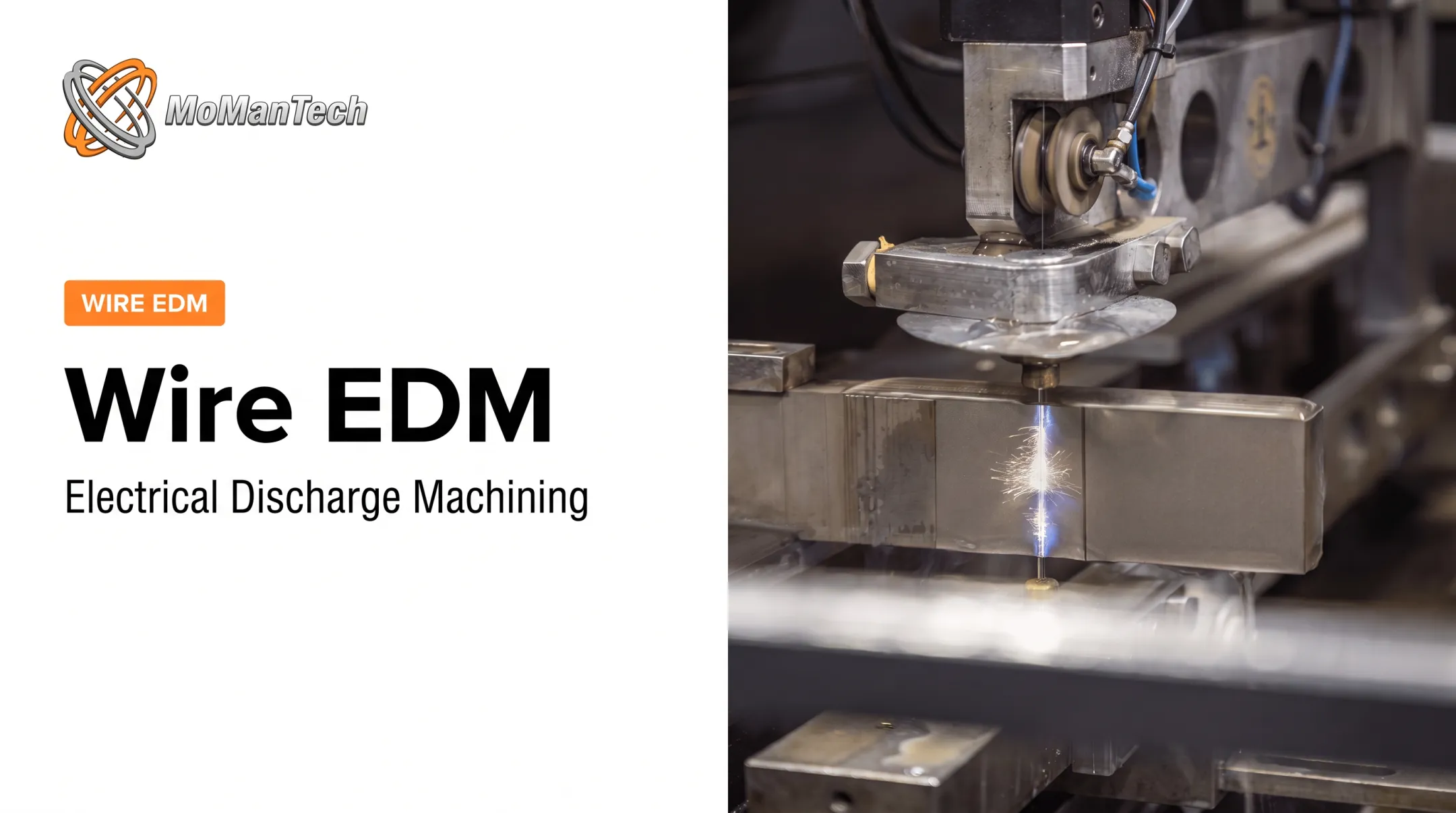
Wire EDM tolerance is the permitted dimensional variation around a nominal size or location on a drawing. The process itself removes conductive material through controlled electrical discharges between a traveling wire electrode and the workpiece — there's no cutting tool making physical contact.
That non-contact setup is the practical upside. Without cutting forces, there's no tool deflection to compensate for, so wire EDM is often specified for thin walls and delicate geometries. But the process isn't immune to error. Thermal effects, spark-gap variation, wire tension, flushing consistency, and machine movement all still influence the final dimension.
Tolerance Isn't the Same as Accuracy, Repeatability, or Resolution
These terms get used interchangeably, and that's where drawings go wrong:
- Tolerance: the permitted variation around a nominal dimension or location
- Accuracy: how closely a produced feature matches its intended CAD location and size
- Repeatability: how consistently the process reproduces the same result across multiple parts
- Resolution: the smallest programmable or measurable increment — not proof of final part accuracy on its own
- Surface finish: the texture left by discharge erosion; improvable with skim passes, and separate from dimensional tolerance
A machine rated for a 0.1-micron programmable increment isn't automatically holding 0.1-micron part tolerance. Makino's own UPN-01 specification sheet lists a 0.1 µm minimum programmable increment alongside a separate ±0.5 µm positioning and repeatability rating — two different numbers describing two different things.
Why Wire Diameter and Kerf Compensation Matter
The programmed toolpath isn't the finished edge. The wire centerline has to be offset from the target edge by roughly the wire radius plus the discharge gap, meaning the nominal kerf runs wider than the wire diameter itself. Get this compensation wrong, and every feature comes out oversized or undersized by a consistent, correctable amount.
That shows up fastest on mating holes, narrow slots, thin profile walls, and fine-featured surgical instrument components, where a few microns decides whether the part assembles. Put tight tolerance callouts on features that control fit, alignment, or strength, not on every dimension by default.
Range of Wire EDM Tolerances and Factors That Influence It
Tolerance range is a process outcome, shaped by machine limits and real operating conditions, not a single fixed number that applies to every job.
Nominal Operating Range
Published figures vary widely depending on what's being measured and under what conditions:
| Source | Figure | Context |
|---|---|---|
| Mitsubishi MP-series | ±2 µm (±0.000079 in) | 20mm-thick hardened PD613 steel, 0.2mm brass wire, room held at 20°C ±1°C |
| Makino UPN-01 | ±0.5 µm positioning/repeatability | Specialty micromachining platform, axis rating |
| Modern Machine Shop illustrative example | ±0.0001 in (±2.54 µm) | 3-inch-thick carbide, with 5-microinch Ra requiring six to seven skim passes |

Notice the pattern: every tight figure comes attached to a specific material, thickness, wire size, and controlled environment. None of these transfer directly to a different part without confirming the same conditions apply.
Allowable Tolerance and Boundary Limits
The drawing sets the boundaries: upper and lower size limits, positional requirements, profile tolerances, and geometric relationships the supplier has to hit and prove.
A very tight tolerance on every feature isn't just unnecessary; it drives up cycle time, finishing requirements, and inspection cost for no functional benefit. Reserve the tightest callouts for features where fit or function actually demands them.
What Actually Moves the Number
- Material properties – electrical and thermal conductivity, hardness, and heat treatment affect spark stability, recast layer thickness, and dimensional consistency.
- Thickness and geometry – taper, thin walls, deep cuts, narrow slots, and small internal radii all change what's achievable, as do starter-hole requirements for enclosed profiles.
- Process controls – wire tension, spark parameters, flushing pressure, dielectric condition, and workpiece alignment.
- Finishing strategy – rough cuts versus skim passes; more finishing passes improve size, geometry, and finish, but add time.
- Environment and time – ambient temperature swings, stress relief in the stock, wire breakage, and machine wear.
Temperature control is easy to underestimate. Modern Machine Shop notes that a 2°F shop temperature swing can shift a 12-inch part by as much as 0.00016 inch. That is enough to blow through a ±0.0001-inch target entirely. That's why demanding tolerance work often requires holding ambient temperature within about 1°F.
MoManTech runs Chmer GX360L and Fanuc Oa wire EDM equipment for spinal, trauma, joint, and foot/ankle components, where intricate profiles on conductive materials are the norm rather than the exception. Feature-specific tolerance planning, not a blanket spec, is what makes those jobs repeatable.
How Tolerances Are Specified, Measured, and Validated
A tolerance only means something if the drawing communicates it clearly and the inspection plan can actually confirm it.
Specification and Documentation
Engineers should define nominal dimensions, bilateral or unilateral tolerances, GD&T, datum references, profile requirements, and material condition explicitly, not leave the supplier to interpret intent. ASME Y14.5 governs the drawing language for dimensional and geometric tolerancing, and relying on it consistently avoids ambiguity.
A few practical habits matter here:
- Identify which dimensions actually need wire EDM-level precision and which can carry broader tolerances — don't tighten every callout by default.
- Clarify timing: does the tolerance apply before or after finishing, coating, heat treatment, or cleaning, since a pre-passivation check may read differently post-process?
- Flag critical-to-function features explicitly so the supplier knows where to focus finishing passes and inspection effort.

Measurement and Verification Methods
The right instrument depends on feature size and geometry:
- Vision/optical systems for small edges or features where contact probing might cause distortion.
- CMMs for datum-referenced geometry and accessible internal features.
- Micrometers, bore gauges, and height gauges for straightforward dimensional checks.
MoManTech's inspection floor includes an OGP Flash 302 for vision, CMM, and laser measurement, plus a 14-inch Mitutoyo PHA 14 with DRO. Standard manual gauges cover the rest: micrometers, calipers, indicators, thread rings, plug gauges, and radius gauges. Matching the instrument to the feature matters more than defaulting to whatever's fastest.
A measurement result is only as good as the system producing it. Calibration status, resolution, datum alignment, fixturing, and ambient temperature at inspection all affect whether a reading is trustworthy.
First-article inspection, in-process checks, and final inspection serve different purposes and should not be collapsed into one step.
Supplier Review Checklist
Before releasing production, confirm the supplier can show:
- Machine calibration records and process capability evidence
- Material traceability documentation
- Inspection records tied to specific features, not just a general pass/fail
- A documented nonconformance process
- Capacity to support the quality documentation your program requires
For medical-device OEMs, this is where quality-system alignment carries real weight. MoManTech is ISO 13485:2016-certified and builds inspection into every step rather than relying on end-of-line sampling.
Certification alone still doesn't guarantee a specific wire EDM tolerance on a given feature. That comes down to documented process capability for that material, that geometry, and that setup.
Design Implications, Limitations, and Common Misinterpretations
Wire EDM is excellent for conductive materials and through-cut profiles. It does not replace milling across the board, so knowing where it stops matters as much as knowing where it excels.
What the Process Can't Do
Conventional wire EDM can't produce a truly blind pocket or fully enclosed feature without a wire-entry strategy. The wire has to thread through the material, typically via a starter hole. A perfectly sharp internal corner is also a physical impossibility. The achievable radius is bounded by roughly half the wire diameter plus the spark gap, before accounting for wire deflection. Specify a radius that reflects the wire and settings actually being used, not a theoretical zero.

When to Choose Wire EDM Over Milling
| Favors Wire EDM | Favors CNC Milling |
|---|---|
| Hardened materials | Bulk material removal |
| Narrow slots, intricate profiles | Nonconductive materials |
| Features vulnerable to cutting forces | Extensive 3D contouring |
| Thin, delicate sections | Blind pockets |
Five Misinterpretations Worth Avoiding
- Treating the tightest published capability as a standard production guarantee: a best-case demo figure and a repeatable shop tolerance are different claims.
- Confusing machine resolution with finished-part accuracy: a fine programmable increment doesn't guarantee that precision shows up on the part.
- Assuming hardness is the only variable: conductivity, thermal behavior, and geometry matter just as much.
- Ignoring temperature and measurement uncertainty: a tight spec checked at the wrong temperature can read out of spec for reasons unrelated to the cut.
- Specifying extreme tolerances on non-critical features without a functional reason: it adds cost without adding value. Involving your machining partner in design-for-manufacturability review before the drawing is locked catches most of these issues early. Tolerances, radii, starter holes, and datum schemes are far cheaper to adjust on paper than after production tooling is set.
Conclusion
Wire EDM supports tight tolerances on conductive, intricate, and hardened components. Reliable results still depend on the whole system:
- Machine capability and setup
- Material, thickness, and geometry
- Programming and finishing strategy
- Environmental control
- Inspection method used to confirm the result
The most useful tolerance on a drawing isn't the smallest number a machine can theoretically hit. It's the one tied to how the part actually functions, backed by a documented and repeatable way to verify it.
For engineers and medical-device OEMs working on spinal, trauma, joint, or foot/ankle components, review critical features, GD&T, and inspection requirements before the drawing is locked. Aligning those details early with a manufacturing partner like MoManTech usually saves far more time than it costs.
Frequently Asked Questions
What tolerances can wire EDM reliably achieve?
Reliable tolerance depends on the machine, material, thickness, geometry, finishing passes, and inspection method. Best-case figures like ±2 µm come from controlled demos on specific materials, so confirm your supplier's production capability for your part.
What is the minimum diameter of wire used in EDM?
Wire diameter varies by machine and application. Common sizes run about 0.2–0.25 mm; specialty micromachining can use wire down to roughly 0.02 mm, which enables finer detail but can reduce stability and speed.
How does material affect wire EDM tolerances?
Conductivity, thermal behavior, composition, and heat treatment affect spark stability, recast layer, and dimensional consistency. Hardened steel, titanium, and softer alloys often need different parameters and finishing passes to hold the same tolerance.
What is the difference between wire EDM accuracy and tolerance?
Tolerance is the allowed variation around a nominal dimension; accuracy is how closely the feature matches its intended size or location. Repeatability and measurement uncertainty both affect whether a reading reflects the part's true dimension.
Can wire EDM hold the same tolerance across an entire part?
Not necessarily. Thickness, taper, geometry, fixturing, and thermal conditions can change performance across one part, so confirm capability on critical features with your supplier instead of assuming uniform tolerance.