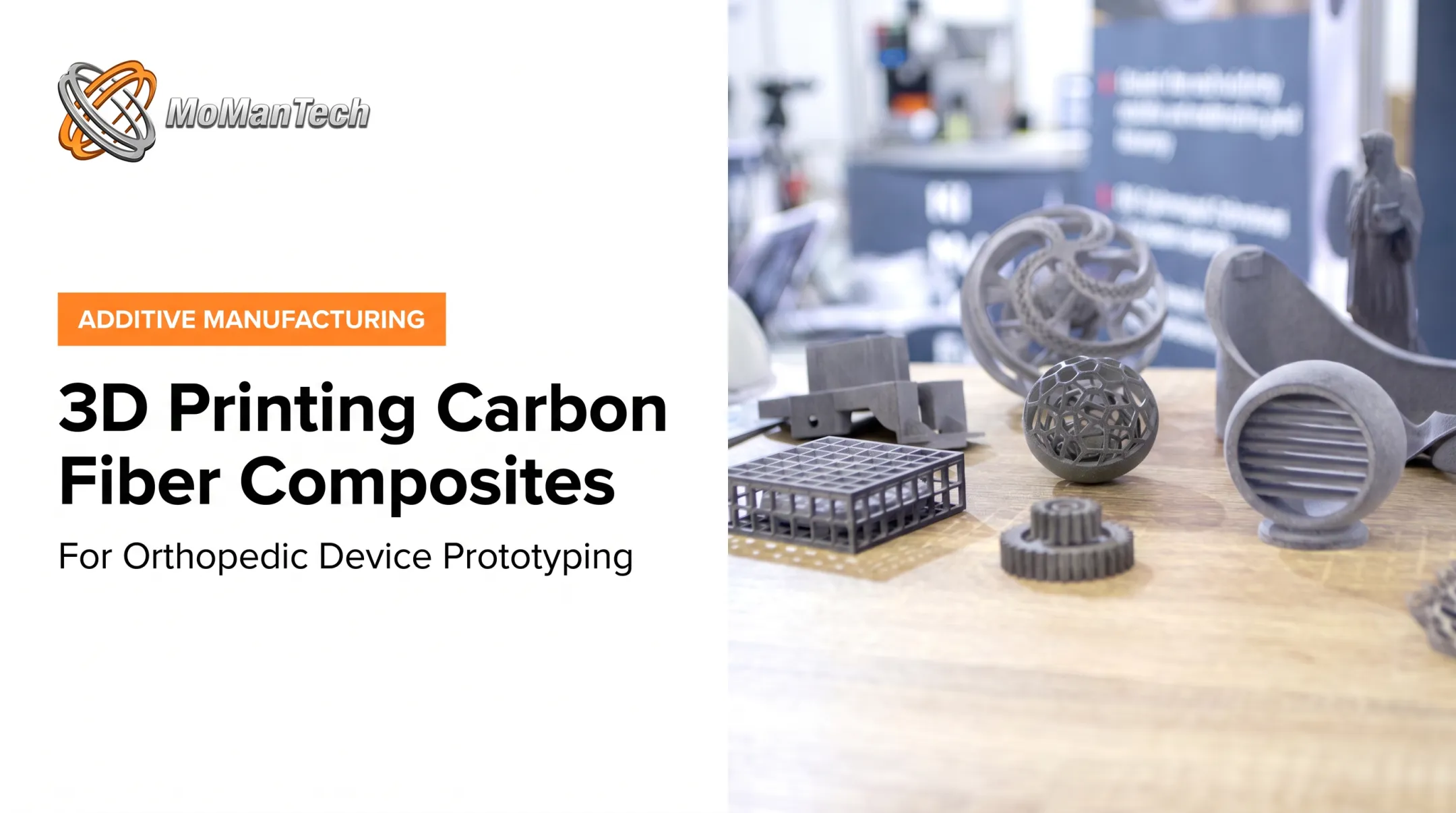

The hard part isn't printing the part. It's choosing the right approach. Standard thermoplastics, chopped-fiber filaments, and continuous-fiber systems all behave differently once fiber orientation, layer adhesion, and process settings enter the picture. A part that tests strong in one direction can fail predictably in another.
This guide covers the materials, the printing technologies behind them, design and quality considerations, common applications, and a practical framework for deciding whether composite 3D printing fits your project.
Key Takeaways
- Composite 3D-printed parts pair a polymer matrix with reinforcement such as carbon fiber, glass fiber, or Kevlar.
- Chopped-fiber filaments improve stiffness with easier access; continuous fiber needs specialized equipment for targeted strength.
- Fiber direction, moisture control, and nozzle selection all shape final part performance.
- Best fit: lightweight tooling, fixtures, prototypes, and low-volume parts where the added complexity pays off.
What Is 3D Printing Composites?
What Is Composite 3D Printing?
A composite 3D-printed part has two components working together: a matrix and a reinforcement. The matrix (typically nylon, ABS, PLA, PETG, or a higher-performance polymer) gives the part its shape, binds everything together, and transfers load into the reinforcement.
The reinforcement—whether chopped fibers mixed into the filament or continuous strands routed through specific layers—adds the mechanical or thermal properties the base polymer can't deliver alone.
Why reinforce at all? Because an unreinforced thermoplastic often can't hit the target spec. Composite reinforcement can improve:
- Stiffness and dimensional stability under load
- Wear resistance in moving or contacting surfaces
- Heat performance at elevated service temperatures
- Strength-to-weight ratio for weight-sensitive designs
Composites Are Not Uniformly Strong
Engineers new to composite printing often miss this: a reinforced part is not automatically stronger in every direction. Layer-by-layer deposition creates anisotropy, or directional strength differences.
Fiber-reinforced parts tend to perform best in the printed XY plane and considerably weaker through the Z direction, regardless of how fibers are arranged within a given layer. Design around this, not against it.

Common Composite Categories
- Polymer-matrix composites: thermoplastics like nylon, ABS, PLA, PETG, or high-performance polymers serving as the base matrix
- Particle-filled materials: additives improving wear resistance, appearance, conductivity, or processability
- Fiber-reinforced materials: chopped, aligned, or continuous carbon, glass, or aramid fibers for directional strength
A note on datasheets: the tensile strength listed for a filament rarely matches the strength of your finished part. Print orientation, fiber content, porosity, and post-processing all move the needle. Always verify manufacturer claims against independent testing for your specific geometry and orientation, not just the spec sheet number.
Composite 3D printing isn't a universal substitute for traditional composite layup, injection molding, forging, or precision machining. The right process still depends on geometry, production volume, tolerance requirements, certification needs, and end-use risk.
How Composite 3D Printing Works: Materials and Technologies
The typical workflow runs from requirements definition and CAD design through material selection, slicing, printing, post-processing, inspection, and functional testing. Each stage has its own failure points, but the material and technology choice made early on shapes everything downstream.
Chopped-Fiber Filament Printing
Short fibers, often less than 1 mm long, are mixed directly into a thermoplastic filament and deposited through a standard FFF/FDM printer. This approach fits into familiar extrusion workflows and improves stiffness and dimensional stability compared to unreinforced polymer.
The tradeoffs are real, though:
- Fiber orientation is far less controlled than in continuous systems
- Surfaces can be rougher, and flexibility often drops
- Abrasive fibers wear standard brass nozzles quickly
- Reinforcement efficiency is lower than continuous fiber
Continuous-Fiber Printing
A second deposition path places intact, continuous carbon, glass, or aramid fiber within the thermoplastic matrix, typically through a dedicated print head. Software can route that reinforcement along actual load paths, around holes, or within selected layers, rather than scattering it uniformly throughout the part.
The structural payoff can be substantial. Stratasys reports 111 MPa tensile strength at break for an optimized unidirectional XY toolpath on FDM Nylon 12CF, compared to just 32.7 MPa for a standard ZX-oriented specimen under identical test conditions.

The manufacturer is clear that the optimized figure isn't representative of typical parts. Still, the gap shows how dramatically orientation and fiber routing affect real-world strength.
Continuous-fiber systems demand more: specialized equipment, path-planning software, and design expertise most shops don't have on day one.
Other Relevant Technologies
Not every reinforced material belongs to the same process family:
- SLS with filled powders — carbon-fiber-filled nylon powder fused layer by layer with a laser, good for functional parts without support structures.
- Resin-based and direct-ink processes — ceramic-filled photopolymers or resin-fed continuous fiber, where dry fiber is wetted with liquid resin at the printhead and cured after deposition.
- Automated fiber placement/hybrid systems — combine traditional composite layup precision with additive flexibility for larger structural parts.
These processes aren't interchangeable. Each produces a different combination of fiber volume, surface finish, and mechanical consistency.
What to Verify Before Choosing a Process
Before committing to a material or machine, confirm:
- Hardened nozzles and wear-resistant feed components rated for abrasive fibers
- Heated beds and controlled or enclosed chambers for thermal management
- Dry storage and filament drying capability for moisture-sensitive polymers
- Software that controls fiber path, orientation, and infill — not just standard slicing
- Build volume, tolerance, and surface-finish compatibility with your part
Match matrix and reinforcement to the use case:
- Carbon fiber for maximum stiffness
- Glass fiber for a balance of performance and cost
- Aramid fiber when toughness and impact resistance matter more than rigidity
Always confirm these tendencies against current technical data for the specific product you're specifying.
Designing, Printing, and Validating Composite Parts
Design for additive manufacturing starts with the same questions every structural design should ask: What loads will this part see? How might it fail? What temperatures, chemicals, or impacts will it face? What are the dimensional requirements?
Orienting Parts Around Load Paths
Print direction, shell strategy, infill pattern, and fiber placement all interact. Route reinforcement to match how the part is loaded:
- Align continuous fiber with primary tensile forces
- Place reinforcement on faces that see bending
- Run fiber concentrically around holes and fastener locations
- Use gradual transitions between reinforced and unreinforced regions; sharp changes create stress concentrations
Practical design moves that reduce failure risk:
- Add fillets and chamfers at stress concentration points
- Keep wall thickness appropriate for the reinforcement type
- Design support-aware geometry to simplify overhangs
- Avoid abrupt fiber-to-no-fiber transitions near load-bearing features
A light part is not automatically a qualified structural part. Run simulation, prototype builds, and mechanical testing—and iterate the design—before a composite print takes real load.

Process Controls That Affect Quality
Four controls make or break part consistency:
- Dry and condition materials per supplier instructions; moisture-sensitive polymers differ by formulation
- Select wear-resistant nozzles and monitor extrusion consistency over time
- Use material-specific temperature, speed, cooling, and chamber settings instead of unreinforced-polymer defaults
- Track build orientation, material lot, and machine settings so runs stay repeatable
ASTM F3489-23 covers static mechanical testing for material-extrusion polymer specimens and calls out anisotropy, porosity, material conditioning, build orientation, and test conditions as result-shifting variables. Test the printed construction itself—not the material name on the spool—to know what you actually built.
Common Defects and Causes
| Defect | Likely Cause | Prevention/Detection |
|---|---|---|
| Delamination | Poor interlayer bonding | Adjust temperature, check fiber coating adhesion |
| Voids | Incomplete fusion during deposition | Optimize print speed, verify fiber wetting |
| Warping | Uncontrolled thermal shrinkage | Use heated chamber, proper bed adhesion |
| Fiber misalignment | Incorrect toolpath planning | Review load paths in slicer before printing |
| Rough surfaces | Chopped fiber protrusion, layer lines | Post-process finishing, adjust layer height |
Post-Processing and the Medical Device Distinction
After the build, finishing usually means trimming, sanding, machining, and sometimes sealing or heat treatment. Dimensional checks, visual inspection, and functional testing follow where the application warrants them.
For medical device teams, one control line is non-negotiable: composite-printed prototypes, fixtures, and development aids are not held to the same controls as patient-contacting or implantable components.
When those prototypes lead into precision-machined orthopedic production, you need an inspection-driven manufacturing environment. MoManTech runs an ISO 13485:2016-certified facility for orthopedic spine, trauma, large joint, and foot/ankle components—the machined parts that often follow composite prototyping. Composite 3D printing itself remains outside that production scope.
Applications and Choosing the Right Approach
Composite 3D printing fits best where strength-to-weight, targeted reinforcement, and fast iteration matter most:
- Medical-device development aids — functional prototypes for instrument and component design review before final manufacture
- Lightweight tooling and fixtures — jigs, holding fixtures, and custom shop tooling that need quick iteration
- Form-and-fit prototypes — geometry and assembly checks before committing to production methods
- Low-volume or replacement parts — short runs where molding tooling cost cannot be justified
- Automation components — end-of-arm tooling and light structural elements on fixtures or cells
- Adjacent R&D uses — brackets, housings, and test fixtures in aerospace or automotive development programs
- Weight-critical custom parts — frames and equipment where stiffness and mass both drive performance
It's especially useful for complex geometries, rapid design iteration, low-to-moderate quantities, and parts where reinforcement only needs to target specific zones rather than the entire structure.
When Another Process Fits Better
Composite 3D printing is usually the wrong fit for:
- Very high production volumes where injection molding tooling pays for itself
- Extremely tight tolerances beyond typical additive capability
- Highly polished surface finish requirements
- Demanding certification pathways requiring established material qualification
- Complex multi-directional loading beyond what layer-based anisotropy can handle
A Practical Selection Checklist
Before committing to composite 3D printing, run through:
- Mechanical and environmental needs — strength, stiffness, toughness, heat, chemicals, and electrical behavior
- Load direction — and how much anisotropy the application can tolerate
- Part specs — size, geometry, tolerances, surface finish, and quantity
- In-house or partner capabilities — printer, material, post-processing, inspection, and testing
- Regulatory requirements — traceability, biocompatibility, sterilization, or customer standards
Total project cost extends well beyond filament price. Factor in:
- Machine time and failed builds
- Maintenance and post-processing
- Inspection and testing
- Design iteration cycles
Whether composite printing saves money versus another process depends on that full stack, and the answer differs by project.
Frequently Asked Questions
What is composite 3D printing?
Composite 3D printing is additive manufacturing using a matrix material combined with a reinforcement, such as chopped or continuous carbon fiber, glass fiber, or Kevlar. The reinforcement adds targeted mechanical or thermal properties the base polymer lacks on its own.
Can you 3D print composite materials?
Yes, many composite materials print successfully, but compatibility depends on the matrix, reinforcement type, printer hardware, nozzle material, and thermal controls. Not every printer handles every composite formulation.
What are examples of composite materials?
Common examples include carbon-fiber-reinforced nylon, glass-fiber-reinforced polymers, Kevlar-reinforced matrices, and particle-filled thermoplastics. Exact formulations and performance vary significantly by supplier, so check current technical data before specifying.
What is the hardest material to 3D print with?
Difficulty depends heavily on the printer and application rather than one universal "hardest" material. High-temperature polymers, moisture-sensitive materials, abrasive fiber blends, and shrink-prone formulations each present distinct processing challenges.
Can composite 3D prints handle functional end-use loads?
Yes, when reinforcement type, fiber direction, and matrix match the load path. Continuous-fiber and high-fill chopped-fiber parts often reach stiffness and strength suitable for fixtures, instruments, and many functional components; validate against your specific mechanical and environmental requirements.